Holiday Shipping and Support Update
Our office will be closed for the Christmas holidays from 24th December to 2nd January 2026. We will be back from the 5th of January.
We wish you a Merry Christmas and a Happy New Year!
Request Demo Device
This allows you to test and evaluate the product under real conditions before making a purchase decision
The following conditions apply:
1. Return Obligation
At the end of the test period (2 weeks), the demo device must be returned unsolicited and at the customer's expense in perfect condition, including accessories and packaging, as an insured package.
2. Liability for Damage / Loss
During the test phase, the customer is liable for loss of or damage to the device and the accessories supplied. 3. No Transfer to Third Parties
The demo unit may not be transferred or rented to third parties.
4. For Testing Only – No Permanent Loan
The unit is provided strictly for testing and evaluation purposes. Use in continuous operation, productive environments, or resale is not permitted.
5. Subject to Availability
Demo units are provided free of obligation and subject to availability. There is no legal claim to receiving a demo unit. Demo units are only available to customers located within the European Union.
6. One-Time Demo per Product/Customer
As a rule, only one demo unit per product and customer is provided.
Best Price Guarantee
Send us the supplier's written offer or the website where the product is offered at a lower price to benefit from this guarantee.
The best price guarantee does not apply to offers from remaining stock or excess stock or to offers from countries outside the EU.
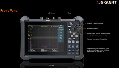
The SIGLENT SHA800A , a handheld portable spectrum analyzer and cable and antenna analyzer is a powerful and flexible tool for those field and outdoor RF applications Including communication engineering, telecom operation and maintenance, radio management, factory production, education and teaching and many other fields. Professional accuracy with flexible analysis capabilities and the ability to make measurements where you need them with a complete portable solution.
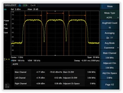
With a frequency range up to 7,5 GHz, the analyzer delivers reliable automatic measurements and multiple modes of operation A spectrum analyzer, including built in amplifier and independent signal source , fast scanning speed, high sensitivity, can achieve broadcast monitoring, channel power scanning, wireless interference location, power monitoring, electromagnetic compatibility, and other functions.
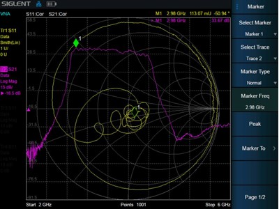
A cable and antenna tester including built in DC voltage bias, with a 1 path 2 port vector network analysis function, can measure TDR, VSWR , port matching debugging, insertion loss measurement, tower amplifier debugging, cable fault location, Smith chart, etc.
Features and benefits
Spectrum analyzer frequency range from 9 kHz up to 7.5 GHz 165 dBm /Hz. Displayed average noise level (Typ 10 4 dBc/Hz.@10 k Hz offset phase noise (1 GHz Typ.), 1 Hz up to 10 MHz Minimum resolution bandwidth (RBW) preamplifier and independent signal source up to 7.5 GHz , GPS positioning and logging
Cable and antenna Test frequency range from 100 kHz up to 7.5 GHz, distance to fault and time domain analysis
Vector network analyzer B ias out up to 32VDC
Typical working time 4 hours, 3.2 kg net weight, 8.4 lnch multi touch screen , mouse and keyboard supported
| Overview | SHA851A | SHA852A |
|---|---|---|
| Frequency range (spectrum analysis) (cable/antenna test) | 9 kHz - 3.6 GHz 100 kHz - 3.6 GHz | 9 kHz - 7.5 GHz 100 kHz - 7.5 GHz |
| Ports | 2 | 2 |
| Frequenzy resolution | 1 Hz | 1 Hz |
| Dynamic range | 100 kHz - 1 MHz: 102 dB, 108 dB (typ.) 1 MHz - 1.5 GHz: 109 dB, 114 dB (typ.) 1.5 GHz - 3.6 GHz: 107 dB, 112 dB (typ.) | 100 kHz - 1 MHz: 102 dB, 108 dB (typ.) 1 MHz - 1.5 GHz: 109 dB, 114 dB (typ.) 1.5 GHz - 3.6 GHz: 107 dB, 112 dB (typ.) 3.6 GHz - 6.5 GHz: 105 dB, 109 dB (typ.) 6.5 GHz - 7.5 GHz: 102 dB, 107 dB (typ.) |
| Setting range of output level | -40 dBm - 0 dBm | -40 dBm - 0 dBm |
| Touch-Display |
You will find the specifications of the SHA800A series here
Ports
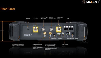
RF input Port 2: N type female, 50 Ω nom
Source Port 1: N type female, 50 Ω nom
USB Host: USB A plug, version 2.0
Ear Phone: Jack 3.5 mm
USB Device USB: C plug, version 2.0
LAN: LAN VXI11 10/100 Base RJ 45
GPS Antenna (GPS Receiver): SMA (F) 3.3V, 50 Ω
Bias out (SHA850-BIAS): SMB (F) 12 V - 32 V 0.1 V step
10 MHz reference input: 10 MHz, 5 to +10 dBm, BNC type female, 50 Ω (nom.)
External trigger input: 1 KΩ 5 V TTL level , BNC type female
GPS
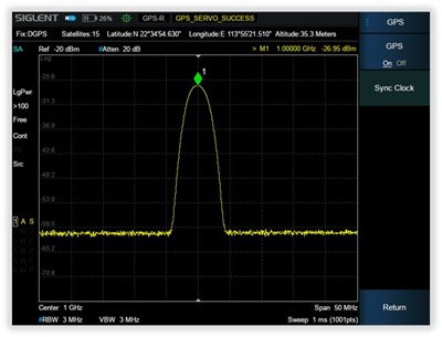
GPS Location and trace log recorder , sync 10 MHz reference clock
Area for "GPS display information“
Area for "GPS satellite lock icon“
GPS display information:
Fix: Invalid / Estimated: Unknown system /
GNSS: global navigation satellite system /
DGPS: differential global positioning system
Satellite: number of Satellites
Latitude
Longitude
Altitude
*Requires GPS Antenna and GPS Receiver Option. GPS Logging Option for saving data.
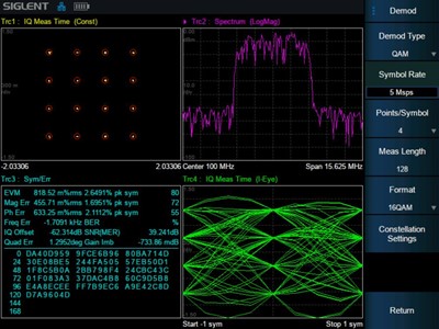
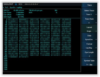
Signal Modulation Analysis
Analog signal: AM/FM/PM (AMA Option)
Digital signal: ASK/FSK/PSK/QAM (DMA Option)
EVM (Error Vector Magnitude) Calculation
Transmission quality factors
Visualization modes include eye-diagrams and constellations
Extends troubleshooting to complex signals and systems
*Requires AMA / DMA Option
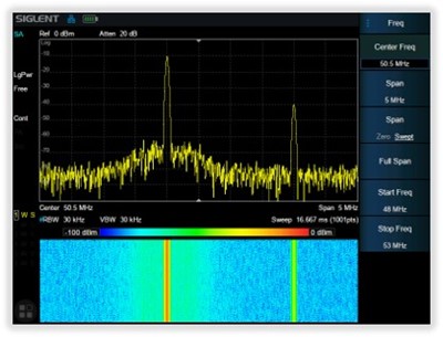
Spectrum Monitor
Color represents spectral energyV
The X axis is frequency
The Y axis is time Also called Spectrogram or Waterfall Chart
Detecting non-continuous and frequency hopping signals
We can observe the change of the signal over a longer period of time
*Requires AMK (Advanced Measurement Kit) Option
Wide range of applications thanks to new accessories
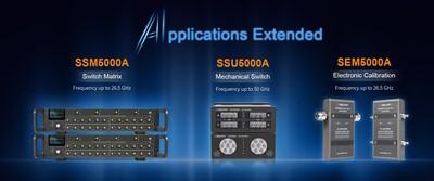
Broaden the possibilities for your analysors SEM5000A series electronic calibration (ECal) modules, SSU5000A series mechanical switch and SSM5000A series switch matrix, which are designed and optimized for use with the SHA850A, SVA1000X and SNA5000A series vector network analyzers from SIGLENT. They offer a comprehensive, cost-effective total solution for simple to complex RF measurement tasks on multiport and multiple devices.Common
Price
Article Group
Manufacturer
Spectrum Analyser
Max. frequency
RBW
DANL
Display Size
Features
Best Price Guarantee
Send us the supplier's written offer or the website where the product is offered at a lower price to benefit from this guarantee.
The best price guarantee does not apply to offers from remaining stock or excess stock or to offers from countries outside the EU.
Request Demo Device
This allows you to test and evaluate the product under real conditions before making a purchase decision
1. Return Obligation
At the end of the test period (2 weeks), the demo device must be returned unsolicited and at the customer's expense in perfect condition, including accessories and packaging, as an insured package.
2. Liability for Damage / Loss
During the test phase, the customer is liable for loss of or damage to the device and the accessories supplied. 3. No Transfer to Third Parties
The demo unit may not be transferred or rented to third parties.
4. For Testing Only – No Permanent Loan
The unit is provided strictly for testing and evaluation purposes. Use in continuous operation, productive environments, or resale is not permitted.
5. Subject to Availability
Demo units are provided free of obligation and subject to availability. There is no legal claim to receiving a demo unit. Demo units are only available to customers located within the European Union.
6. One-Time Demo per Product/Customer
As a rule, only one demo unit per product and customer is provided.
Application
Communication Engineering
- Comparative measurement of received signal power
- Fast location of interference signals
- Installation and maintenance of base station
- Cable and antenna measurement
- Wireless equipment field test
- Field strength coverage measurement
- Telecom drive test operation and maintenance
Failure Analysis in the field
- Characterize RF devices
- Characterize electronic components including
- Resistors, Capacitors, Inductors…
- Filters, Cables, Mixers, Connectors…
- Antennas, Amplifiers, Attenuators…
Device parameter Verification
- Measure the characteristics of amplifiers, mixers, filters and other devices in the field
- Test the performance, bandwidth, intermodulation distortion and many other indicators
Site Installation & Troubleshooting
- Site survey
- Radio link installation
- Site acceptance
- Design and assembly troubleshooting
Telecom drive test operation and maintenance / Installation and maintenance of cellular systems
Fault diagnosis and maintenance to ensure the continuity of communication.
Most microwave link equipment problems are related to cables, antennas and connectors.
If the performance of the feeder is degraded, it may lead to problems such as:
Reduced coverage
Link failure
Decreased sensitivity of the receiver path
Radio Monitoring Management
In applications such as communication and commercial microwave backhaul
- Hardware installation and maintenance
- Detecting the quality of wireless signals
- Periodically detect unexpected signals
- Signal monitoring
Example
- Detecting low-level signals or neighboring small interference signals under strong signal conditions requires high dynamic range.
- While the latter requires excellent phase noise performance.
Station Installation Verification
- Verify station parameters including frequency and power
- Debug cables and connections
- Characterize active and passive devices including amplifiers and antennas
- Conduct on-site verification and followup
Downloads
Datasheet
Siglent SHA850A Series
Language: English
Version: EN_02B
File Size: 1.51 MiB
Release Date: 19.02.2024
Siglent directional antenna ANT
Language: English
Version: EN_02A
File Size: 1.10 MiB
Release Date: 07.06.2016
Manual
Siglent SHA800A Series Quick Start Guide
Language: English
Version: EN01A
File Size: 1.84 MiB
Release Date: 11.11.2024
Siglent SHA850A Series
Language: English
Version: EN_01C
File Size: 8.51 MiB
Release Date: 09.07.2024
Guide
Siglent SHA850A product information
Language: English
Version: E01A
File Size: 1.71 MiB
Release Date: 26.04.2023
Spectrum Analyzer IVI-C Programming guide
Language: English
Version: E01A
File Size: 1.36 MiB
Release Date: 16.10.2023

