
Accessory PicoScope 5000 MSO
11 of 11 Article
The PicoScope 5000E series is the first 4-channel USB oscilloscope to feature 16-bit resolution, low noise, and a high dynamic range. This allows it to measure low-amplitude signals that other oscilloscopes cannot capture. With 16-bit resolution on all four channels, the PicoScope 5000E series features a high-performance ADC for capturing low-amplitude signals, power supply ripple, distortions, and other subtle millivolt transitions. This enables engineers to achieve high measurement accuracy in analog systems.
Supported by the advanced PicoScope 7 test and measurement software, the PicoScope 5000E series enables fast and cost-effective debugging and performance validation of complex analog and power electronics designs. Furthermore, it offers an ideal package for many other applications, including embedded system design, research, testing, education, service, and repair.
Today, engineers must measure smaller signals in systems with higher noise levels: ripple in the millivolt range on DC buses, low-level sensor outputs, precision audio, analog front ends, medical electronics, and mixed-signal designs where a rare glitch can be just as critical as the main waveform. The 16-bit resolution of the PicoScope 5000E series offers an industry-leading noise level of less than 22 µV root mean square (RMS) and a total harmonic distortion (THD) of better than −73 dB. This high dynamic range helps engineers maximize usable resolution and detect components with small amplitudes, ripple, distortion, and anomalies that may be overlooked by devices with lower resolution or higher noise levels.
| PicoScope 5000E Series | 5462E 5462E MSO | 5463E 5463E MSO | 5464 5464E MSO |
|---|---|---|---|
| Input channels | 4 analog, plus 16 digital on MSO models | 4 analog, plus 16 digital on MSO models | 4 analog, plus 16 digital on MSO models |
| Bandwidth (–3 dB) | 60 MHz | 100 MHz | 200 MHz |
| Rise time (10% to 90%, −2 dBFS) | 5.8 ns | 3.5 ns | 1.75 ns |
| Selectable bandwidth limits | 20, 60 MHz | 20, 60, 100 MHz | 20, 60, 100, 200 MHz |
| Vertical resolution | 16 bits | 16 bits | 16 bits |
| Sample rate | 2.5 GSa/s | 2.5 GSa/s | 2.5 GSa/s |
| Waveform capture rate | 2,000,000 wfms/s | 2,000,000 wfms/s | 2,000,000 wfms/s |
| Waveform generator | |||
| Logic analyzer | (on MSO models) | (on MSO models) | (on MSO models) |
You can find all specifications here

Buying a PicoScope is not like making a purchase from other oscilloscope companies, where extras increase the price. With these scopes, high-end features such as serial decoding, mask limit testing, advanced math channels, segmented memory, hardware-based time-stamping and a signal generator are all included in the price. To protect your investment, both the PC software and firmware inside the scope can be updated.

To support modern embedded system development, both the 5000E and 5000E Plus ranges include Mixed Signal Oscilloscopes (MSO). These models augment the four analog channels with 16 digital inputs, allowing for simultaneous observation of logic states and analog waveforms. This integrated approach enables engineers to correlate bus protocol data (such as I2C, SPI or CAN) directly with physical layer phenomena like ringing, crosstalk or power supply droop, all within a single time-aligned display.

Custom probes enable you to scale sensor and transducer readings to their real-world values. You can adjust the software to account for gain, attenuation, offsets and non-linearities. Once the correct scaling and units have been configured, the system displays real-world data directly. This eliminates the need for manual calculations. For complex inputs, such as non-linear temperature sensors, advanced lookup tables can be used to convert measured voltages into temperatures in degrees. The setup process is efficient and flexible. The software will guide you through configuring the channel settings, including coupling, voltage range, and filtering, to match your hardware. The software includes definitions for standard Pico probes. Furthermore, you can store user-generated probes for later use. These settings are stored within .psdata files, allowing you to share your configurations with other users.

Precision starts at the probe tip. The 5000E Series features a meticulous front-end design with shielded inputs to eliminate crosstalk and harmonic distortion. With a noise floor as low as 22 μV RMS and a typical channel-to-channel isolation ratio better than 500:1, you can detect microvolt-level signals that are typically lost in the noise floor of lesser instruments. This exceptional signal integrity is backed by improved bandwidth flatness and a 73 dB SFDR, making it the ideal tool for stabilizing precision power rails or analyzing sensitive sensor data.

With a noise floor as low as 22 µV RMS, the PicoScope 5000E Series ensures even the smallest amplitude signals remain measurable and clear. When paired with 16-bit vertical resolution, the superior signal-to-noise ratio makes it an essential tool for high-precision signal analysis. Trust the data that you see with more than 73 dB of SFDR, exceptional crosstalk rejection and superior bandwidth flatness. This wide dynamic range means complex signals can be captured with precision. When paired with the powerful features of the PicoScope 7 software, it uncovers hidden signals with ease.
Analyze large data sets quickly with a fast USB-C connection that keeps the display responsive, even with millions of data points on screen. Automatically measure each cycle in a waveform, or view signal pulses and frequency spectra side by side. To isolate rare events, memory segmentation combines with rapid trigger mode to capture thousands of waveforms in quick succession. These can be viewed in the waveform buffer navigator where you can scroll and zoom through them to find glitches. You can also filter using mask limit testing or measurement limits to display the waveforms you need to see. More advanced tools, such as serial decoding and DeepMeasure™, work to analyze data packets or events across all waveform buffers in the deep memory, making the PicoScope 5000E Series some of the most capable oscilloscopes on the market.

PicoScope oscilloscopes can decode more than 40 data protocols, with more in development, including CAN, UART, I2C, LIN, MODBUS and more. All protocols are built-in as standard and available free of charge as part of software upgrades. See the full list of protocols in the technical specifications. On MSO models, you can decode up to 4 analog and 16 digital channels of serial data, giving you the flexibility to decode multiple buses simultaneously. Graph format shows the decoded data (in hex, binary, decimal or ASCII) in a data-bus timing format beneath the waveform on a common time axis, with error frames marked in red. These frames can be zoomed to investigate noise or signal integrity issues. Table format shows a list of the decoded frames, including the data and all flags and identifiers. You can set up filtering conditions to display only the frames you are interested in or search for frames with specified properties. The statistics option reveals more detail about the physical layer such as frame times and voltage levels if appropriate. More than 40 serial protocol decoders as standard in PicoScope oscilloscopes. PicoScope can also import a "Link File" spreadsheet to decode the data into user-defined text strings. This helps to speed analysis by cross-referencing hexadecimal field values into human readable form. So, for example, instead of displaying “Address: 7E” in the Table View, the corresponding text "Set Motor Speed" will be shown instead

Advanced serial filtering is built into the serial protocol decoder. You can isolate specific packets of interest within the serial protocol decoder, for the analysis of large datasets captured via deep memory. You can apply cumulative filters to the decoding table using logical operators (such as equal to or contains) on specific fields; for example, isolating I2C traffic to display only Write operations. Additionally, the tool supports data indexing, enabling you to filter for specific byte ranges within a data payload (e.g. columns 0–1). Applying these filters updates the tabular data list and simultaneously generates a secondary trace on the graph display, visualizing only the filtered values directly beneath the complete packet data.
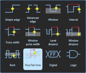
Many digital oscilloscopes still use a trigger architecture based on analog comparators. This causes time and amplitude errors that cannot always be calibrated out and often limits trigger sensitivity at high bandwidths. In 1991 Pico pioneered the use of fully digital triggering using the actual digitized data. This technique reduces trigger errors and allows these oscilloscopes to trigger on the smallest signals, even at the full bandwidth. Trigger levels and hysteresis can be set with high precision and resolution. The reduced rearm delay provided by digital triggering, together with segmented memory, allows the capture of events that happen in rapid sequence. Rapid triggering can capture waveforms at a rate of 2 million wfms/s, until the buffer is full.

The PicoScope 5000E Series offers a set of advanced trigger types including pulse width, runt pulse, windowed, rise/fall time, logic and dropout that function across the full scope bandwidth. The pulse width direction control specifies whether you want to trigger on positive, negative or either-polarity pulses, and the dropout trigger control specifies whether to trigger when the signal remains high, low or in either state relative to the threshold. The digital trigger available on MSO models allows you to trigger the scope when any or all of the 16 digital inputs match a user-defined pattern. You can specify a condition for each channel individually, or set up a pattern for all channels at once using a hexadecimal or binary value. The logic trigger function also allows you to trigger on combinations of edge or window triggers on any of the analog inputs, for example to trigger on edges on channel A only when channel B is also high, or to trigger when any of the four channels go outside a specified voltage range.

The PicoScope 5000E Series features hardware-based trigger time-stamping and frequency counting. Each waveform can be time-stamped with the time from the previous waveform, with the resolution of a single sample interval, and the trigger signal frequency can be displayed with up to 7 digits of precision. Rapid trigger rearm times are possible, down to < 700 ns on the fastest timebase

Some oscilloscopes struggle when you enable deep memory. The screen update rate slows and the controls become unresponsive. The PicoScope 5000E Series avoids this limitation with the use of a dedicated fourth-generation hardware acceleration (HAL4) engine inside the oscilloscope. Its massively parallel design effectively creates the waveform image to be displayed on the PC screen and allows the continuous capture and display of up to 2 billion samples every second. The hardware acceleration engine eliminates any concerns about the USB connection or PC processor performance being a bottleneck.

All PicoScope 5000E models have a built-in function generator covering the frequency range from 100 μHz to 20 MHz. As well as basic controls to set level, offset and frequency, more advanced controls allow you to sweep over a range of frequencies, while spectrum peak-hold options enable amplifier and filter response testing. Trigger features allow one or more cycles of a waveform to be output when various conditions are met, such as the scope triggering, a trigger event on the aux input or a mask limit test failing. All models also include a 14-bit 200 MS/s arbitrary waveform generator (AWG). AWG waveforms can be created with the built-in editor, loaded from a spreadsheet or exported as a CSV file.

High sampling rates are meaningless if they can only be sustained for microseconds. The PicoScope 5000E models solve this with a massive 1 Gpts capture memory (2 Gpts for Plus models in 8-bit mode). This allows the device to maintain its maximum 2.5 GSa/s (5 GSa/s for Plus models in 8-bit mode) sampling rate for a full 200 ms duration. Whether you are capturing a second-long power-up sequence or searching for a single high-speed transient buried in a long data stream, the 5000E Series provides nanosecond time resolution without forcing you to compromise on your capture window or vertical accuracy.

The PicoScope 5000E Series features a USB-C SuperSpeed connection to the host computer, providing power for the scope with a single USB-C cable. To retain compatibility, a USB-A to USB-C cable is also supplied, along with an external power adaptor for use with USB ports which can't supply the full power requirements of the scope. The USB connection allows high-speed data acquisition and transfer, while making printing, copying, saving and sharing your data quick and easy. PicoSDK® supports continuous USB streaming to the host computer at rates of over 300 MS/s.
PicoScope PC-based oscilloscopes use the host computer’s display, which is typically larger and of higher resolution than the dedicated displays installed in traditional benchtop scopes. This allows for simultaneous display of time- and frequency-domain waveforms, decoded serial bus tables, measurement results with statistics and more. PicoScope software scales automatically to take full advantage of the improved resolution of larger screens, including 4K models. It allows engineers to get more done in less time through split-screen views of multiple channels or different views of the same channel. And, it can show multiple oscilloscope and spectrum analyzer traces at once. Large, high-resolution displays make it easy to view the high-resolution signals achieved with the PicoScope 5000E Series. With a 4K monitor, PicoScope can display more than ten times the information of traditional scopes. Elements such as measurements, serial decoding or scope traces can be undocked from the main window and moved to another screen to take full advantage of multi-monitor setups.

The spectrum view plots amplitude against frequency and is ideal for finding noise, crosstalk or distortion in signals. The spectrum analyzer in PicoScope is of the Fast Fourier Transform (FFT) type which, unlike a traditional swept spectrum analyzer, can display the spectrum of a single, non-repeating waveform. With up to a million points, PicoScope’s FFT has excellent frequency resolution and a low noise floor. PicoScope can display a spectrum plot of all active channels simultaneously, with a maximum frequency up to the bandwidth of your scope. You can display multiple spectrum views alongside oscilloscope views of the same data. A comprehensive set of automatic frequency-domain measurements can be added to the display, including THD, THD+N, SNR, SINAD and IMD. A mask limit test can be applied to a spectrum and you can also use the AWG and spectrum mode together to perform swept scalar network analysis.
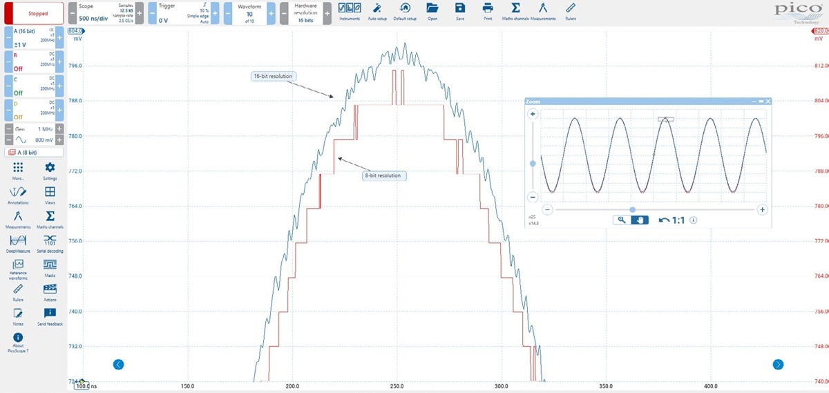
For applications that demand precision or speed, the PicoScope 5000E Plus features switchable 16-bit or 8-bit resolution. 16-bit mode increases vertical precision for detailed voltage readings. 8-bit mode boosts bandwidth and sampling rates to capture fast edges and digital signals without aliasing. In 8-bit mode, the PicoScope 5000E Plus increases the sampling rate to 5 GSa/s, enabling precise timing verification. Capture high-speed digital signals with time resolution down to 200 ps and analyze them with the powerful PicoScope 7 software.

Language: English
Version: MM145.en-1
File Size: 7.41 MiB
Release Date: 20.05.2026
Language: German, English, Chinese, Spain, French, Italian
Version: DO396-2
File Size: 4.63 MiB
Release Date: 12.05.2026