
Accessories, Batronix Magnova BMO
13 of 13 Article
Modern embedded systems combine analog signals, digital interfaces and increasingly complex communication protocols. The BMO200-EMB has been configured specifically for these challenges.
Two BMO-MSO logic probes expand the Magnova to up to 16 digital channels, transforming it into a powerful mixed-signal oscilloscope. Interfaces such as I²C, SPI, UART, CAN and LIN can be analyzed alongside analog signals, making relationships between signal integrity, supply voltages and data traffic immediately visible.
The package is complemented by the comprehensive Sensepeek 6027 All-in SQ350 Kit. Its hands-free probes enable stable measurements even on densely populated PCBs and allow multiple signals to be monitored simultaneously over extended periods. The combination of advanced mixed-signal analysis and practical measurement accessories makes the BMO200-EMB an ideal platform for development, troubleshooting and verification of modern embedded systems.
| Features | Magnova BMO200-EMB |
|---|---|
| Channels | 4 |
| Bandwidth | 200 MHz (upgradable to 350 MHz) |
| Sample rate | 1.6 GSa/s when using channel 1 and/or 2 1.0 GSa/s with additional use of channel 3 and/or 4 |
| Waveform capture rate | 300,000 wfms/s (12,000,000 wfms/s History Mode) |
| Memory depth | Single-channel mode: 320 Mpts Dual-channel mode: 160 Mpts Four-channel mode: 80 Mpts |
| Integrated decoders | I²C, SPI, UART, CAN, CAN-FD, LIN and Parallel |
You will find the specifications of the Magnova here.

Two BMO-MSO modules provide a total of 16 digital channels in addition to the analog inputs. Communication interfaces, control signals and signal timing relationships remain visible within the same time context.

Modern embedded systems consist of many interconnected signals. The combination of analog channels, digital channels and protocol decoders helps engineers identify root causes faster and better understand system interactions.

The professional Sensepeek measurement system enables stable measurements even on densely populated PCBs. Multiple signals can remain connected and monitored over extended periods, making it ideal for debugging, protocol analysis and troubleshooting.
| Magnova BMO Sets | Bandwidth | Channel | Logic Analyzer | Waveform Generator | Foot Switch | MSO Demo Board |
|---|---|---|---|---|---|---|
| BMO100-EDU | 100 MHz (upgradable to 350 MHz) | 4 | Option | Option | ||
| BMO200-EMB | 200 MHz (upgradable to 350 MHz) | 4 | Option | Option | Option | |
| BMO350-LAB | 350 MHz | 4 | Option |
The BMO200-EMB expands the Magnova with two BMO-MSO logic probes, providing a total of 16 digital channels. Analog waveforms, digital control signals, and communication interfaces can be captured, displayed, and analyzed simultaneously.
In embedded systems, faults often arise from the interaction between multiple analog and digital signals rather than a single source. The BMO200-EMB keeps these relationships visible within the same time context, making it easier to understand and troubleshoot complex hardware systems.

Serial interfaces such as I²C, SPI, UART, CAN, CAN FD, LIN, and parallel buses can be decoded directly within the Magnova. Decoded data remains linked to the corresponding analog and digital waveforms.
This allows communication errors, timing issues, and signal anomalies to be analyzed together. Engineers can see not only what data was transmitted, but also how supply voltages, signal integrity, and logic states behaved at exactly the same moment.
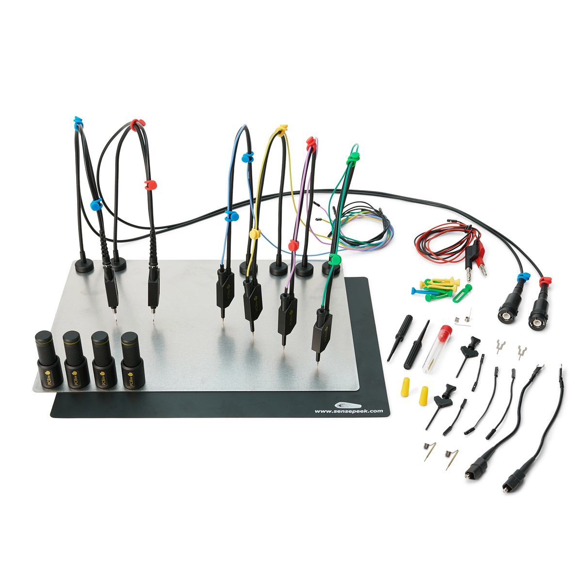
The included Sensepeek 6027 PCBite Kit enables stable, hands-free measurements on densely populated PCBs. Probes can be positioned with precision and remain securely in place, even during extended measurement sessions.
This makes it easy to monitor multiple signals simultaneously without having to hold probes manually. Especially during embedded debugging, protocol analysis, and hardware troubleshooting, measurement setups remain organized, repeatable, and easy to manage.

The large 15.6-inch Full HD touchscreen provides ample space for analog channels, digital channels, protocol decoders, measurements, and analysis tools to be displayed simultaneously. This helps maintain a clear overview, even during complex mixed-signal measurements.
For embedded development, this simultaneous visibility is particularly valuable. Control signals, bus communication, supply voltages, and analog effects can all be observed together without constantly switching between different views.


The Magnova performs triggering entirely in the digital domain using the acquired measurement data. Even the smallest signal events can therefore be detected with exceptional precision and reliably captured using adjustable hysteresis.
Combined with analog and digital channels, this enables detailed analysis of sporadic faults, critical timing conditions, and unexpected signal behavior. Especially in embedded systems, precise triggering helps reveal rare events in a reliable and repeatable way.

High-performance 12-bit analog-to-digital converters, a powerful 16-bit system architecture, and an exceptionally low-noise front end ensure that even the smallest signal details remain clearly visible.
This is particularly valuable in embedded development, where digital communication, supply voltages, and analog interference often need to be analyzed together. Noise, overshoot, coupling effects, and signal integrity issues become easier to identify and understand.

With up to four simultaneous FFT channels, waterfall display, peak tables, and markers, the Magnova provides detailed insight into signals in the frequency domain.
Interference, switching frequencies, harmonics, and coupling effects become immediately visible. In embedded systems, FFT analysis helps engineers identify the sources of unwanted signals and better understand the relationship between digital switching activity and analog behavior.

With up to four independent counter and digital voltmeter (DVM) instances, together with integrated trend charts, the Magnova supports long-term monitoring of frequencies, voltages, and signal stability.
This is especially valuable when investigating sporadic faults, drift, temperature effects, or unstable operating conditions. Even rare events can be captured while relevant measurement values are continuously monitored and systematically analyzed.
Here you will find the videos we have already published on the Batronix Magnova oscilloscope. They show various functions of the Magnova – from FFT and decoding to generator functions and Bode plot measurements.
Most of the videos were recorded directly via the Magnova's DisplayPort output using video capture. They show the behavior and display that can also be seen on the device's screen. In the videos, we use a mouse for operation so that a clearly visible mouse pointer is available. Operation via the Magnova's touch display works in much the same way.
The most recent videos are at the top of the list and show the latest enhancements from the latest firmware updates.
This video shows some of the new features introduced with firmware update 1.8.1:
This video shows some of the new features introduced with firmware update 1.7.1:
This video shows some of the new features introduced with firmware update 1.6.9:
Introductory video for the launch of the generator module:
An entertaining example of the Magnova's XY mode – and at the same time a good impression of the system's performance:
General overview of the device and its functions during introduction:

Language: German
File Size: 3.64 MiB
Release Date: 06.02.2026
Language: English
File Size: 3.64 MiB
Release Date: 06.02.2026
Language: English
Version: 1.20
File Size: 772.41 KiB
Release Date: 21.08.2025
Language: English
Version: 1.8
File Size: 566.09 KiB
Release Date: 09.07.2026
Language: German
Version: 1.2
File Size: 5.23 MiB
Release Date: 21.08.2025
Language: English
Version: 1.2
File Size: 5.05 MiB
Release Date: 21.08.2025
Language: English
File Size: 661.64 KiB
Release Date: 17.07.2026

Language: German, English
Version: 1.9.3
File Size: 53.36 MiB
Release Date: 20.07.2026